Services
- EDM/WEDM machining services
- EDM/WEDM machine maintenance and inspections for ZAPbp (Zakład Automatyki Przemysłowej B.P.) machines as well as in-house machines
- Training on operation of ZAPbp and in-house EDM/WEDM machines
- EDM machine modernization for ZAPbp production
- Replacement of control system with PLC (PP15ster) enabling machining along any straight path in the workspace and along any XY arc (particularly useful for EDM threading)
- Replacement of lead screws with HIWIN ball screws (optionally combined with ACservo drive replacement)
- PCB design
- Based on technical documentation provided by the client
- As part of creating a prototype of the device
- Firmware development. Delivering projects based on controllers using ARM-core microcontrollers (Cortex-M0, M3, M4). Embedded software (depending on project complexity) is implemented as:
- Applications developed in C
- Applications developed in C/C++ based on real-time operating systems: FreeRTOS, RTX, or RTX5
- 3D Printing Services using FDM Technology
- Maximum print size: 220×220×250 mm
- Supported filaments: PLA, PETG, ABS, ABS kevlar, TPU
Knowledge base
EDM (Electrical Discharge Machining) is a process designed to reproduce the shape of an electrode (a tool made of copper or graphite) in an electrically conductive workpiece (the eroded material). The electrical erosion process is based on generating high-current electrical discharges occurring between the electrode and the workpiece in a dielectric environment. Therefore, there must always be a certain working gap (from 0.05 mm to 0.1 mm) between the surfaces of the electrode and the workpiece – the process takes place “without contact”, meaning there is no mechanical contact between the tool and the workpiece. In the case of sinker EDM machines, the dielectric is most commonly a liquid produced from highly purified petroleum fractions.
Electrical Discharge Erosion
In order to describe the stages of occurrence or development of a single discharge, it is first necessary to know what type of current block is being used. In most cases, this type determines the default electrode/workpiece polarity, which in turn defines which current (ionic or electronic) will have the dominant influence on the EDM process.
The two basic types of power supplies are RC and transistor-based. The former is now considered an obsolete, almost “museum-grade” solution (although it is still used in certain specific cases). Therefore, for the purpose of describing the stages of a single discharge, I will assume the use of the latter.
EDM using transistor-based generators relies on the use of an ionic arc as the dominant energy carrier. Since the process is based on an ionic arc, it is carried out using relatively long pulses (>150 µs) with the following polarity: electrode (+), workpiece (-).
In the simplest terms, the operating principle of such a power supply is as follows: the workpiece is connected to the system GROUND, while the electrode is connected to the generator's power output. The control unit sends a rectangular clock signal to the pulse generator, determining how long the power transistors remain switched on or off, thereby enabling or blocking current flow between the electrode and the workpiece.
Stages of discharge initiation:
- The electrode approaches the workpiece to the “ignition” distance, i.e. the distance at which a spark can occur,
- The power transistors in the current block are switched on, causing a high voltage to appear on the electrode,
- As a result of the large potential difference between the electrode and the workpiece, an electromagnetic field is created between them. Its intensity is greatest where the distance between the workpiece and electrode surfaces is smallest (it should be remembered that no surface is perfectly flat – it always has microscopic protrusions and depressions). In the area of the highest field intensity, the dielectric liquid becomes polarized to a level at which the resistance of that area drops to a “critical” value, allowing current to flow,
- The discharge begins with the ignition of an electron arc, i.e. the emission of electrons from the workpiece material and their movement towards the electrode,
- The cloud of electrons colliding with dielectric molecules (hydrocarbon chains) causes them to break down into hydrogen and carbon molecules. At a later stage, an electron is “stripped” from the hydrogen atoms, resulting in the appearance of “free” protons in the discharge space, i.e. positively ionized particles. Accelerated by the electromagnetic field, these protons begin to move towards the workpiece, forming an ionic arc. Since the discharge space contains a cloud of “free” electrons and protons, a plasma channel is formed,
- The positively charged ions accelerated by the electromagnetic field collide with the surface of the workpiece, transferring their kinetic energy to the workpiece, where it is converted into thermal energy. Localized melting of the workpiece material occurs, with the local temperature rising to as much as 14,000°C,
- As the temperature increases in the discharge area, a bubble of vaporized dielectric forms around the plasma channel,
- The power transistors in the current block are switched off, causing the flow of electrons to stop,
- Due to the very large pressure difference between the surroundings and the inside of the bubble containing vaporized dielectric, the bubble implosively collapses inward. As a result, the locally molten workpiece material is ejected into the dielectric, where it forms into almost perfectly spherical particles,
- The dielectric is re-ionized.
The next discharge occurs at another location that is, at that particular moment, the most optimal one… and this is how the specified volume of workpiece material is gradually removed.
Applications of EDM
Where is EDM used today? Due to the low productivity of the process compared with other conventional machining methods (such as milling or turning), it is primarily used where everything else fails, namely:
- for precision machining of difficult-to-cut materials such as titanium alloys, hardened steels, cemented carbides and other modern alloys (e.g. Inconel),
- when the machining process must be non-contact, which minimizes the risk of cracking or deformation of the workpiece,
- for producing deep, narrow and complex cavities (in injection molds or dies) that cannot be accessed with a milling cutter,
- for non-standard machining operations such as producing threads in difficult-to-cut materials or profiling the working surfaces of diamond/CBN wheels,
- when minimizing the depth of changes to the internal structure of the material is important to us (similarly to laser cutting or plasma cutting, EDM is based on melting the material. However, unlike these other methods, the material is melted to a depth of no more than 0.2 mm. Therefore, if the workpiece material is hardenable, only a thin outer layer will become hardened).
The electrical discharge erosion process is based on generating high-current electrical discharges occurring between the electrode and the workpiece in a dielectric environment. EDM operating parameters are therefore primarily related to controlling the transistor-based current block, whose power output is connected to the electrode. The control system sends a rectangular clock signal to the pulse generator, determining how long the power transistors are switched on/off, thereby enabling/blocking the flow of current between the electrode and the workpiece. Thus, we have three basic settings:
- pulse duration: the duration of the discharge,
- pause duration: the duration of the interval between consecutive discharges,
- current: the amplitude of the current flowing through the plasma channel during the discharge,
These parameters allow us to influence machining efficiency, surface roughness, electrode wear and the size of the lateral gap.
Additionally, we have auxiliary parameters responsible for the stability of the machining process: working threshold and short-circuit threshold (specified in %).
EDM Machining Efficiency
The basic characteristic describing the operation/behavior of the current block is its machining efficiency characteristic. Below is an example plotted for the following conditions:
- Workpiece material: ST steel
- Dielectric: cosmetic-grade kerosene
- Electrode: copper (M1E) rod, diameter ø16 (S≈200mm2)
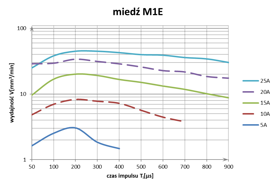
The data used to plot the above characteristic were normalized to continuous operation conditions (without the use of periodic electrode lifting). The general conclusions drawn from their analysis are as follows:
- Increasing the current value increases machining efficiency (the higher the current, the greater the volume melted from the workpiece during a single discharge),
- Increasing the pulse duration increases machining efficiency until a certain maximum is reached,
- The pulse duration at which the highest efficiency is achieved for individual current settings oscillates around Ti=200μs
Surface Roughness
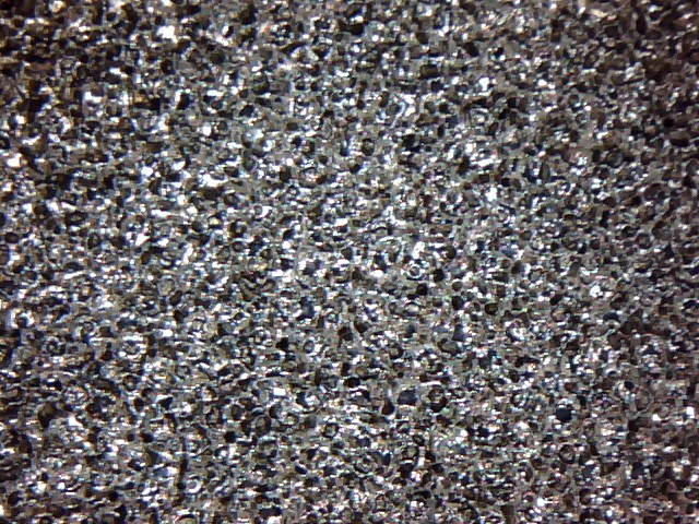
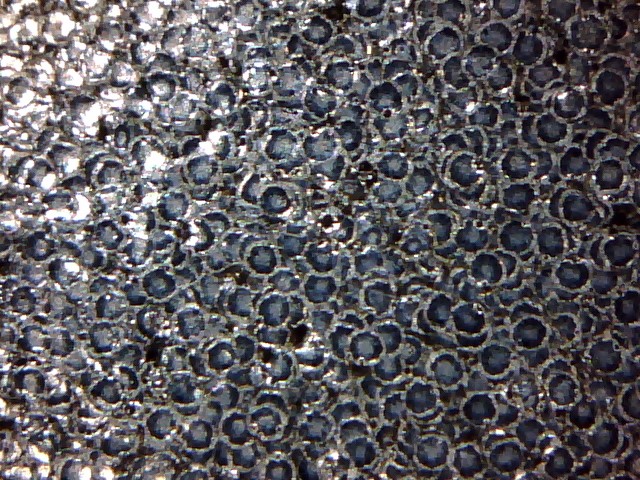
The Ra surface roughness characteristics as a function of pulse duration have a shape similar to the efficiency characteristics:
- Increasing the current value increases surface roughness,
- Increasing the pulse duration increases surface roughness until a certain maximum is reached, after which the roughness decreases due to the appearance of “smeared craters”.
For I=5A; Ti=200us:
For I=5A; Ti=900us:
Electrode Wear
The wear of a copper electrode depends on:
- melting of the electrode material, resulting from a mismatch between the average current density flowing through the electrode and its ability to dissipate heat. As a practical “workshop conversion factor” for EDM, we conventionally assume 0.2A/mm2. In reality, electrode wear resulting from melting of the electrode material is primarily influenced by its shape and volume, followed by such settings as current, pulse duration and pause duration. Taking an electrode with a working surface area of 28mm2 (which conventionally gives us the possibility of setting a maximum of 5.6A) and setting the current to 20A, we will obtain different effects depending on whether the electrode is a cylinder with a radius of 3mm or a rectangular prism with a base of 0.5×56mm. In the first case, we will observe wear of the edges without wear of the “front face”. In the second case, the electrode will wear by 50%,
- the number of discharges required to erode a given volume – the fewer discharges that occur, the lower the electrode wear. Here, we primarily consider the moment when the current arc is initiated – the “cleaner” the initiation is (free from relaxation oscillations and unwanted current “spikes”), the better the electrode life. Each discharge (for electrode (+), workpiece (-) polarity) begins with the ignition of an electron arc, i.e. the emission of electrons from the workpiece material and their movement towards the electrode. Accelerated in the electromagnetic field, the electrons collide with the surface of the electrode material, transferring part of their kinetic energy to it, where it is converted into thermal energy. Localized melting of the electrode material occurs, which in turn causes its erosion.
Setting the “current” parameter with regard to electrode wear represents a balance between two causes of electrode degradation. If the current is too high, the electrode will undergo excessive melting. If it is too low, a greater number of discharges will be required to remove the specified volume, exposing the electrode to greater erosion caused by the ignition of electron arcs.
Pause Duration
The pause duration between pulses is required to properly extinguish the preceding discharge and cool the area surrounding it to a temperature below 180˚C (this is the lower boiling point limit of cosmetic-grade kerosene; falling below this temperature is necessary for the process to proceed correctly). Shortening the pause duration directly increases machining efficiency, but if its value is too low and flushing of the gap is ineffective, it may lead to the occurrence of so-called “burn marks”.
Working Threshold and Short-Circuit Threshold
To explain what these two “mysterious” settings are, we should first note that the only significant difference between an EDM control system and those used in other CNC machines is the presence of a so-called “spark control” system. This system provides feedback to the PLC controller, based on which the controller determines whether it can move the machine's working head at the set speed, whether it should stop, or whether it should even retract, all in order to maintain an appropriate gap between the electrode and the workpiece. The “spark control” system generates feedback based on statistical analysis of the potential difference between the electrode and the workpiece for a specified number of “pulses” (in this case understood as the number of periods during which the power transistors in the current block are switched on, i.e. the number of periods during which a discharge may occur). Assuming that the power transistors are switched on one hundred times within a given period, each such “switch-on” may result in one of three states: no discharge, a proper discharge occurs, or a short circuit occurs (i.e. physical contact between the electrode and the workpiece). The occurrence of each of these states is counted and then compared with the values specified by the settings. If 30 proper discharges occur out of 100 specified “pulses”, and the operator has set the “working threshold” to 20%, the PLC controller will receive information that it should stop the movement of the working head due to an excessive frequency of discharges. A similar situation applies to the “short-circuit threshold”: if 30 detections of contact between the electrode and the workpiece occur out of 100 specified “pulses”, and the “short-circuit threshold” is set to 20%, the PLC controller will receive information that it should retract the working head until the short circuit is cleared.
The working threshold acts as a kind of “muzzle” for the machine – if more discharges occur within a given unit of time than the specified threshold, this means that there is too much material to be removed for the working head to move to the next point of the programmed trajectory. In such a situation, the machine should stop and wait until the number of discharges falls below the specified threshold. If the working threshold is set too low, machining efficiency decreases. If it is set too high, process stability is lost (the machine moves too quickly along its trajectory, resulting in frequent short circuits), additionally increasing the risk of so-called “burn marks”.
The short-circuit threshold, on the other hand, determines how sensitive the machine should be to detecting contact between the electrode and the workpiece. During the machining process, erosion products in the form of small particles of eroded material are generated between the electrode and the workpiece. As they accumulate in the working gap (before being removed by the flushing flow of the dielectric), they may cause short circuits between the electrode and the workpiece. Such events should not affect process stability, so in order to eliminate their influence, we increase the short-circuit threshold, thereby making the machine less sensitive to the occurrence of accidental short circuits.
Setting the Operating Parameters
Setting the operating parameters to achieve maximum EDM efficiency while minimizing electrode wear:
- Determine the maximum current value using the formula I=J∙S, where: S – electrode working surface area, J – limiting current density (for copper J=0.2A/mm2; for graphite J=0.3A/mm2),
- Determine the pulse duration based on the efficiency characteristic,
- The pause duration should not be shorter than tp=Ti/10,
- when machining a material with a high zinc content, tp should not be shorter than Ti/5,
- as flushing conditions deteriorate or in the case of a very small machining area (<10mm2), the pause duration should be increased,
- Set very strong flushing from above for cavities deeper than 5mm.
There are two basic types of pulse generators used in EDM: RC and transistor-based generators. The fundamental difference between them lies in the energy carriers used to melt the material locally during electrical discharge.
RC Generator
The RC generator is the simplest solution developed for EDM machining. In its basic configuration (as the name suggests), it consists of a single capacitor and a resistor. The capacitor is charged through a resistor that limits the current drawn from the power supply and is then discharged (when suitable conditions are present) through a discharge between the electrode and the workpiece. By adjusting the supply voltage, capacitor capacitance, and resistor resistance, we can control the capacitor charging time and the instantaneous current flowing through the gap during discharge. However, we cannot control the pulse duration or the interval between pulses. Discharges occur randomly. Due to its design, machining with RC generators relies on short (<10μs), high-current pulses. Because the pulses are short, we use the electron arc as the dominant energy carrier (and ensure that an ion arc does not develop, which would result in the formation of a plasma channel). In this case, electrons must be emitted from the electrode (polarity: electrode (-), workpiece (+)). Under no circumstances or machining technique can the polarity of an RC generator be reversed; doing so would result in machining the electrode itself and, consequently, excessive electrode wear.
An electron arc carries less energy than an ion arc, which is why machining with an RC generator is characterized by very low material removal rates. Its advantages include:
- simple construction,
- very low surface roughness of the machined material,
- resistance to surface burning (even when materials other than copper or graphite are used for the electrode).
Transistor-Based Generator
In my designs, I use a so-called "two-stage transistor-based generator" consisting of two sections:
- ignition stage: essentially a single resistor switched by a power transistor; it is a high-voltage source that delivers an appropriate amount of current to the system to initiate a discharge,
- main current stage: a bank of transistors connected in parallel and operating as a current source; once the discharge has been initiated, it supplies the gap with the preset current.
Machining with transistor-based generators relies on the ion arc as the dominant energy carrier. Since an ion arc is used, the process employs relatively long pulses (>150us) with the following polarity: electrode (+), workpiece (-).
Operating Principle
The control system sends a rectangular clock signal to the pulse generator, determining how long the power transistors remain switched on or off, thereby enabling or interrupting current flow between the electrode and the workpiece. When the clock signal at the generator input goes high:
- The power transistor in the ignition stage is switched on, causing a high voltage to appear at the electrode,
- If suitable conditions are present, a discharge is initiated. It begins with the formation of an electron arc, meaning that electrons are emitted from the workpiece material and flow toward the electrode,
- The voltage drop between the electrode and the workpiece is detected, providing a signal to activate the main current stage and start timing the preset pulse duration,
- The specified "dose" of current is injected into the established electron arc,
- An ion arc forms as the dielectric molecules are broken down by bombardment from the electron cloud. Since the discharge region contains a cloud of "free" electrons and protons, a plasma channel can be said to have formed,
- The workpiece material melts locally,
- As the temperature in the discharge region rises, a bubble of vaporized dielectric forms around the plasma channel,
- The power transistors in the main current stage are switched off, and the transistor in the ignition stage is switched on, stopping the flow of electrons,
- Due to the very large pressure difference between the surrounding environment and the inside of the vaporized-dielectric bubble, the bubble collapses inward implosively, ejecting the locally molten workpiece material into the dielectric fluid.
Advantages of a transistor-based generator:
- much higher material removal rates compared with RC generators,
- a wider range of achievable surface roughness values for the machined material,
- the ability to machine using an electron arc (which requires reversing the polarity from the default setting and shortening the pulse duration to a maximum of 10μs). This technique is used when machining materials with very high thermal conductivity, such as copper and beryllium.
Disadvantages:
- complex construction,
- susceptibility to surface burning when heat is not properly removed from the machining zone (for example, due to a small machining area or ineffective flushing of the gap).
"Burning" in EDM is the process of heavy hydrocarbon chains depositing on the surface of the workpiece as a result of a sustained plasma arc. It manifests itself as a bright light emitted from beneath the electrode. The result of burning is a tenacious scale that is difficult to remove and damage to the surface of the machined cavity (a substantial depression forms beneath the scale).
When a discharge is initiated, a plasma channel forms, surrounded by a gas bubble generated by the boiling dielectric and consisting of light hydrocarbon fractions. Once the discharge ends, the bubble splits into two parts, which accumulate on the surfaces of the electrode and the workpiece. The pressure difference between the inside of the bubbles and the surrounding environment causes them to collapse inward implosively, ejecting molten workpiece material into the dielectric fluid. Low thermal conductivity of the electrode and ineffective gap flushing (poor heat removal from the surrounding area) prolong the cooling time of the surrounding dielectric until it reaches a temperature below 180˚C (the lower boiling point limit of cosmetic-grade kerosene; cooling below this temperature is necessary for the process to proceed correctly), thereby extending the lifetime of these bubbles. If this time exceeds the interval between successive discharges and a series of discharges occurs in close proximity to the same point, a large volume of gaseous erosion products (dielectric vapors) will be generated. A sustained plasma arc develops when discharges occur in an environment filled with dielectric vapor, where extinguishing the arc becomes problematic.
In general, burning is associated with problems removing heat to the surrounding environment. The following factors contribute to reduced heat dissipation:
- deposition of heavy hydrocarbon fractions onto the electrode during machining, forming a thin layer with low thermal conductivity,
- a small machining area – the smaller the area, the more discharges occur at the same location, resulting in greater localized heating of the area surrounding the discharge,
- ineffective gap flushing.
To prevent burning, you should:
- increase the interval between pulses,
- improve flushing efficiency by using an electrode with a different design, a different flushing method, or additional assist techniques (periodic electrode retraction, orbiting, or electrode vibration).
Material
Due to the widespread use of transistor power supplies in EDM machines, which means the process is run with relatively long pulses (>150us), electrode materials must primarily offer excellent electrical and thermal conductivity. Copper and graphite provide the best balance between these two properties, which is why they are the preferred electrode materials.
Good thermal conductivity affects how quickly heat is removed from the discharge area, reducing electrode wear (caused by melting of the electrode material) and making the process less susceptible to “burns.” Good electrical conductivity directly increases machining efficiency.
| Copper (Cu) | Graphite (C) | |
| Melting point [˚C] | 1083 | 3600 |
| Density [kg/m3] | 8,96×10⁻⁹ | 1,6-1,9 x10⁻⁹ |
| Specific heat capacity [J/(kg*K)] | 386 | 507 |
| Thermal expansion [10-6/K] | 16-18 | 2-6 |
| Thermal conductivity [W/mK] | 400 | 90-140 |
| Resistivity [μΩm] | 0,016-0,02 | 10-20 |
General characteristics of electrode materials in relation to EDM machining:
| Copper (Cu) | Graphite (C) | |
| Melting point [˚C] | To prevent excessive electrode wear (melting), the current density flowing through it should not exceed J=0,2A/mm2. | To prevent excessive electrode wear (sublimation), the current density flowing through it should not exceed J=0,3A/mm2. |
| Density [g/cm3] | High electrode weight. | Low electrode weight. Easy to machine. |
| Thermal expansion [10-6/K] | Low dimensional stability of the electrode at high temperatures. | High dimensional stability of the electrode at high temperatures. |
| Thermal conductivity [W/mK] | Low susceptibility to “burns” | Susceptibility to “burns.” |
| Resistivity [μΩm] | Low power loss, allowing the discharge to be highly concentrated at a point and increasing cavity-sinking efficiency. | High resistivity -> high voltage drop -> high discharge power loss -> reduced efficiency. |
| Copper (Cu) | Graphite (C) | |
| Melting point [˚C] | To prevent excessive electrode wear (melting), the current density flowing through it should not exceed J=0,2A/mm2. | To prevent excessive electrode wear (sublimation), the current density flowing through it should not exceed J=0,3A/mm2. |
| Density [g/cm3] | High electrode weight. | Low electrode weight. Easy to machine. |
| Thermal expansion [10-6/K] | Low dimensional stability of the electrode at high temperatures. | High dimensional stability of the electrode at high temperatures. |
| Thermal conductivity [W/mK] | Low susceptibility to “burns” | Susceptibility to “burns.” |
| Resistivity [μΩm] | Low power loss, allowing the discharge to be highly concentrated at a point and increasing cavity-sinking efficiency. | High resistivity -> high voltage drop -> high discharge power loss -> reduced efficiency. |
Most popular electrode material grades:
| M1E | EDM-3 (HK-3) | EDM1 (HK-75) | EDM200 (HK-20) | |
| Application | General purpose. | Used for the most demanding machining. Recommended for ribs less than 1 mm thick. | Used for finishing and precision work. Recommended for ribs approximately 1 mm thick. | Used for preliminary and rough machining and for sinking large areas. |
| Density [g/cm3] | 8,9 | 1,78 (1,84) | 1,66 (1,82) | 1,82 (1,86) |
| Thermal expansion [10-6/K] | 17,7 | – | – | – |
| Resistivity [μΩm] | 0,016 | 15,6 (15,5) | 19,3 (16,5) | 14,7 (12) |
| Average grain size [μm] | – | <3 (2) | <5 (4) | 10 (6) |
When should you use copper, and when graphite, as an electrode material?
Copper is my first-choice material, mainly because it is less susceptible to “burns,” which is particularly important when sinking deep cavities where erosion debris is difficult to flush out during machining. This provides greater process stability. However, copper is difficult to turn or mill because of its high malleability and ductility, which make chip breaking difficult and cause material to stick to the cutting edge. When a complex shape must be sunk, often with very thin walls (for example, a stylized inscription), I use graphite, mainly because it is easier to produce sharp edges on the electrode. It should be noted, however, that graphite machining usually requires dedicated machines with specially sealed guideways and an efficient extraction system to remove graphite dust quickly. Graphite also has the advantage of price: it is cheaper than copper.
Design considerations
An incorrectly designed electrode can lead to:
- higher manufacturing costs,
- inefficient removal of erosion debris and gases generated during the process from the gap, making the process more susceptible to “burns” and less stable,
- an undesired shape of the machined cavity,
- difficulty positioning the electrode relative to the workpiece.
When designing an electrode, several aspects specific to EDM should be considered:
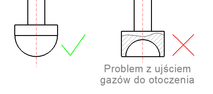
Ease of escape of gaseous erosion products (dielectric vapour) from the gap. Minimize the number of recesses in the electrode shape where gases could accumulate. If they cannot be avoided, provide vent channels to each recess or change the sinking direction from vertical to horizontal,
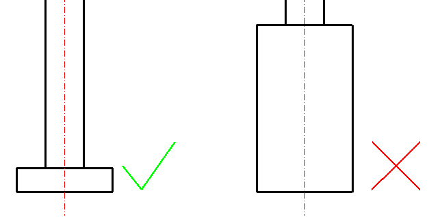
It is recommended to minimize electrode height (shortening the path taken by erosion products as they escape from beneath the electrode and out of the machining area).
Planned gap-flushing method
- If flushing is performed through the electrode, allow space for a flushing hole.
- When sinking with “orbiting,” adjust the electrode dimensions by the diameter of the circle/side length of the square along which the electrode will move during the process (“Orbiting” provides the electrode with a spiral motion. During the process, both the electrode face and its sides are active. This function enables what is known as a moving gap, i.e. an increasing distance between the electrode and the workpiece on the side opposite the active electrode face. A moving gap helps remove gases; as they escape, they draw kerosene and erosion debris along with them).
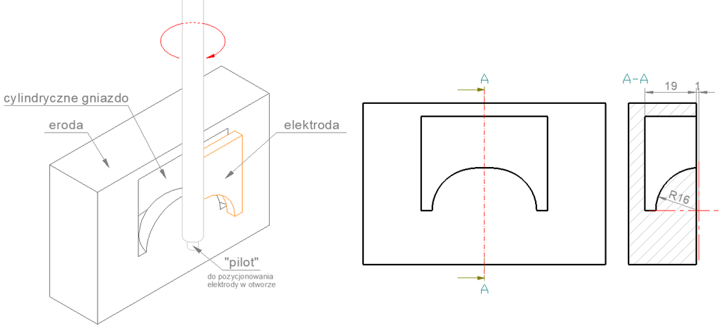
Method of positioning the electrode relative to the workpiece. For electrodes used to sink cylindrical cavities, it is recommended to create a so-called “pilot” that defines the electrode axis and can be used for positioning.
Method of mounting the electrode in the holder
- When an adjustable holder is used, allowing the electrode to be rotated by up to 5° about each axis, a pin in the form of a rod made from an electrically conductive material is attached to the finished electrode (by screwing, press-fitting, or soldering). This pin serves as the gripping point for the electrode.
- Use of EROWA or 3R holders. These holders consist of two parts: a base (two are required, one mounted on the machining-centre table and the other on the EDM spindle) and the holder itself, in which a “raw” piece of copper/graphite is mounted. The holder containing the workpiece is clamped and positioned by the base on the milling machine, and the required electrode shape is machined. The machined electrode and holder are then removed from the base on the milling machine and installed in the base on the EDM machine.
Flushing efficiency directly affects machining performance and process stability. An improperly selected flushing method may result in inefficient removal of erosion debris and gases generated during the process from the machining gap, thereby reducing machining efficiency (due to the occurrence of so-called "indirect discharges", i.e. discharges between the electrode and the erosion debris), producing uneven surface roughness in the cavity, and increasing the susceptibility of the process to "burn marks". Conversely, a dielectric fluid jet that is too strong may increase the frequency of "short circuits" as erosion debris accumulates in the corners of the machined cavity, forming "bridges" between the electrode and the workpiece.
Localized flushing using segmented hoses
This is the most popular flushing method due to its ease of use. Every EDM machine is equipped with at least one segmented flushing hose, which can easily be extended with additional components, such as specialized nozzles or hoses mounted on magnetic bases. However, it should be noted that, when machining with electrodes having a large working surface, localized flushing from one side of the electrode may create uneven flushing conditions within the gap, resulting in varying surface roughness in the cavity. The surface located closer to the nozzle outlet will have greater roughness than the surface on the opposite side of the electrode.
Flushing through the electrode
When using electrode flushing, a flushing hole with a minimum diameter of ø2 must be made in the electrode, and a special holder must be used to supply dielectric fluid through it. Placing the hole at the geometric center of the electrode ensures uniform flushing conditions within the gap and, consequently, consistent surface roughness throughout the cavity. This method is most commonly used for:
- Machining deep, blind cylindrical cavities using a tubular electrode. To maintain the correct cavity shape (which requires machining the material located beneath the flushing hole), orbital movement must be used, or a multi-channel tube must be used as the electrode and rotated during the process.
- EDM threading in blind holes. When performing EDM threading, particular attention must be paid to the dielectric fluid flow rate through the flushing hole. Threading electrodes are highly susceptible to the accumulation of erosion debris in their recesses. Therefore, the flow rate should be kept to a minimum, or any flushing method should be abandoned entirely, allowing dielectric vapors generated during the process to escape from the gap and carry the erosion debris with them.
- Removing broken taps or drills by EDM, where, in addition to flushing away erosion debris, it is necessary to remove detached chips and remnants of the tool being removed from the machining area.
Suction through the workpiece
This is the most effective flushing method, used when the workpiece already has a hole or when a process hole can be made. Positioning this hole at the geometric center of the machined cavity ensures uniform flushing conditions within the gap and, consequently, consistent surface roughness throughout the cavity. At the same time, this is the least popular method because it requires the most work to implement. A suction mechanism is essential. This is most commonly an ejector in the form of a so-called Venturi tube, connected to the end of a segmented hose, together with a fixture that allows the tube's suction inlet to be connected to the flushing hole. In addition, the workpiece must be secured to a suitable support frame that provides access to the flushing hole, allowing a vacuum hose to be connected to it.
Programmed flushing assistance methods
EDM machines are often equipped with additional functions to assist flushing, such as:
- Electrode vibration (designed to generate a standing wave between the electrode and the workpiece, preventing the generated erosion debris from settling at the bottom of the cavity. This function is most often used in combination with the periodic electrode lift function),
- Periodic electrode lift (periodically retracting the electrode from the machining area, drawing in kerosene together with the erosion debris and expelling it from the machining zone),
- Circular or square orbiting (provides spiral movement of the electrode. During the process, both the electrode's end face and its sides are active. This function allows a so-called "moving gap" to form, meaning an increasing distance between the electrode and the workpiece on the side opposite the active electrode face. The "moving gap" facilitates gas removal; as the gases escape, they draw kerosene and erosion debris with them. This method is used for:
- Machining deep, blind, narrow cavities and wherever flushing through the electrode or suction is not possible and localized flushing is insufficiently effective,
- "Opening up" a cavity, i.e. increasing its dimensions.)
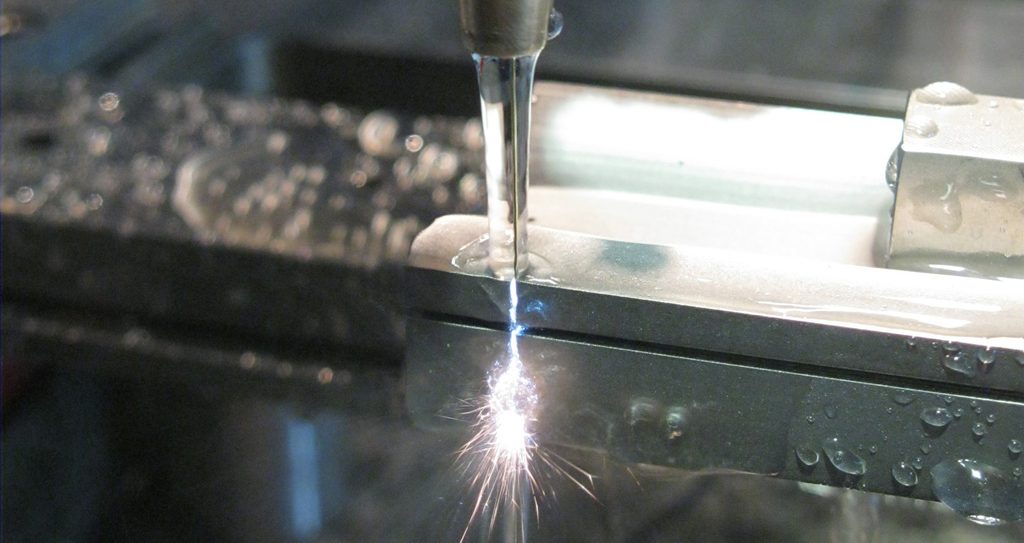
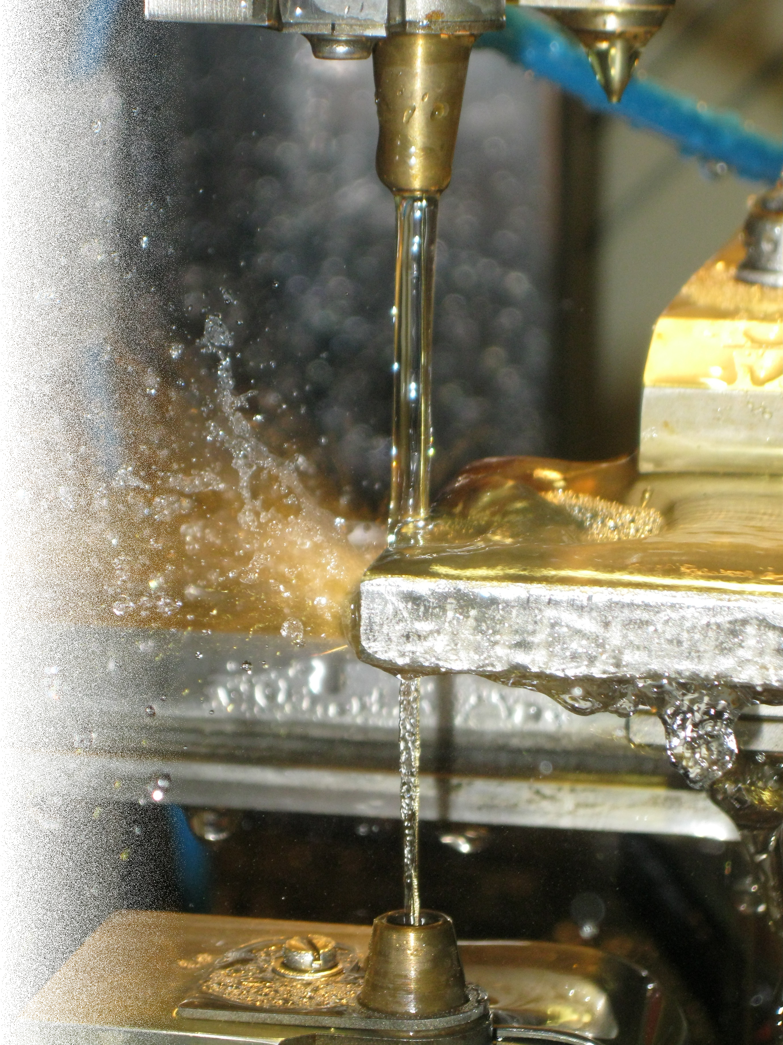
WEDM (Wire Electrical Discharge Machining) is a process used to cut complex shapes in an electrically conductive workpiece using an electrode in the form of a wire (most often brass, 0.1 to 0.3 mm in diameter). Because the part is usually clamped to a stationary table, and the wire is guided through two independently positioned wire guides, it is possible to produce surfaces that are both perpendicular and inclined relative to the table surface. During cutting the wire is continuously fed through, so it can be considered a universal electrode that is not subject to wear. The electrical erosion process is based on generating high-current electrical discharges between the electrode and the workpiece in a dielectric environment. Therefore, a certain working gap (from 0.05 mm to 0.1 mm) must always exist between the surfaces of the electrode and the workpiece – the process takes place "contactlessly", that is, without mechanical contact between the tool and the workpiece. In wire EDM machines the dielectric is most often deionized water with a conductivity of no more than 60 μS.
Electrical erosion in WEDM
To describe the stages of a single discharge, we must first answer the question: what is the fundamental difference between the transistor blocks used for EDM and WEDM?
EDM generators operate by using the ion arc as the dominant energy carrier. Since it is an ion arc, the process is run with relatively long pulses (>150 μs) at the polarity: electrode (+), workpiece (-).
WEDM cutting, on the other hand, uses short (<10 μs) high-current pulses. Here the electron arc is the dominant energy carrier (moreover, an ion arc must not be allowed to ignite, that is, a plasma channel must not form, because this would quickly result in the wire burning through). In this case, the electrons must be emitted from the electrode (polarity: electrode (-), workpiece (+)). Under no scenario or cutting technique can the polarity be reversed – a mistake means a huge drop in cutting efficiency.
The operating principle of such a block, in the briefest terms: the control system sends a square-wave clock signal to the pulse generator, which determines for how long the power transistors are switched on/off, allowing/blocking the flow of current between the electrode and the workpiece.
Stages of a discharge:
- The electrode approaches the workpiece to the "ignition" distance, that is, a distance at which a spark can occur,
- The power transistors in the current block are switched on, causing a high voltage to appear on the workpiece,
- As a result of the large potential difference between the electrode and the workpiece, an electromagnetic field forms between them, with its intensity being highest where the distance between the workpiece and electrode surfaces is smallest (it should be remembered that no surface is perfectly flat – it always has some microscopic bumps/dents). In the area of highest field intensity the dielectric fluid is polarized to the point where the resistance at that spot drops to a "critical" value, that is, one at which current can flow,
- The discharge begins with the ignition of the electron arc, that is, with electrons being emitted from the electrode and flowing towards the workpiece material,
- Accelerated in the electromagnetic field, the electrons collide with the surface of the workpiece, transferring their kinetic energy to it, where it is converted into thermal energy. Localized melting of the workpiece material occurs, with the local temperature rising to as much as 14000°C,
- As a result of the temperature rise in the discharge area, a bubble of vaporized dielectric appears,
- The power transistors in the current block are switched off, ending the flow of electrons,
- Due to the very large pressure difference between the surroundings and the inside of the vaporized dielectric bubble, the bubble collapses implosively inward, as a result of which the locally molten workpiece material is ejected into the dielectric, where it forms into almost perfect little spheres,
The next discharge appears at another location, the most optimal at that moment… and this is how the desired shape is cut.
Applications of WEDM
WEDM machining is used:
- in the precision machining of difficult-to-machine materials such as titanium alloys, hardened steels, cemented carbides and other modern alloys (e.g. Inconel),
- when the machining process must be contactless, which minimizes the risk of cracking or deformation of the workpiece,
- in non-standard machining operations such as WEDM turning,
- in the tooling industry: manufacturing of blanking dies, tools, injection molds and components of complex mechanical systems,
- in the automotive industry: preparing samples for testing in quality control departments, and producing spare parts in maintenance departments,
- in university and research institutions: preparing material samples and manufacturing components for prototype systems.
Contact
Email: poterala.piotr@gmail.com
Phone: +48 507-493-844
Address
gen. Maczka 19/24,99-300 Kutno, Poland
Correspondence address
Bociania 3,99-300 Kutno, Poland
VAT ID: PL7752601355